Product outline
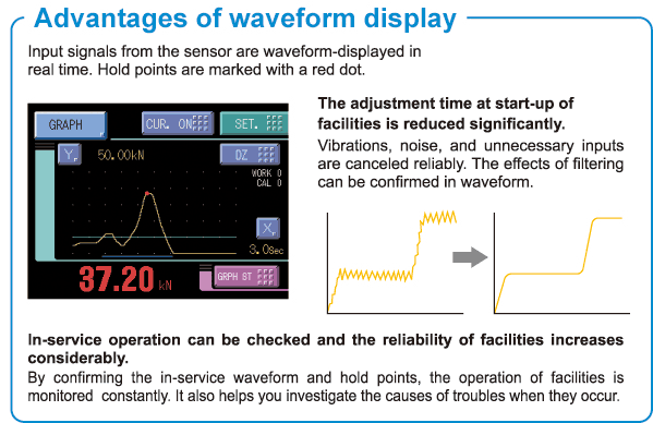
F372A is a digital indicator integrated with a strain gauge sensor that can display physical quantities such as pressure, load and torque in waveforms.
It is able to visually capture in waveforms the fluctuations in physical quantities which are difficult to capture by only numerical values.
With a maximum 2000 times per second for high-speed processing, it is also ideal for narrow value fluctuations and comes equipped with a HI/LO limit comparison function, various hold functions and judgment function.
F372A is the best digital indicator for graders and testers used in results judgment of assembling work and auto machining.
Features
F372A is digital indicator for strain gauge type sensors to measure pressure, load, torque. With various hold functions, they contribute to production line quality control.
Waveform display

Extensive comparison functions
Necessary points in waveform are taken out to make HI/LO limit comparisons.
Operating work*is selected to perform comparison and judgment under various condition settings.
* 16 types of settings per operation (types of hold, HI/LO limit set values) can be stored.
■ Hold types
Sample, Peak, Valley, P-P, Average, Inflection Point, Relative Maximum, Relative Minimum, Relative Difference
■ Section setting
– External section (Peak, Valley, P-P, Average)
– External + Time specified section (Peak, Valley, P-P, Average)
– Level + Time specified section (Peak, Valley, P-P, Average)
– Level (Peak, Valley)
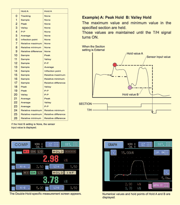
<Double Hold>
Specifically combined two types of hold functions are performed simultaneously in one detection. Hold modes can be selected from 26 modes shown below.

HI/LO limit comparisons of the difference value between the presently measured hold value and the previously measured hold value can be made.
Difference value = Present hold value (indicated value) – Previous hold value
<Relative Value Comparison>
HI/LO limit comparisons of the difference (relative value) between hold value A and hold value B can be made.

Specifications
Analog section|Display section|Setting section|Hold function|Comparison function|Calibration value selection|External signal|Interface|General performance|Attachments
| Analog section | |
| Excitation voltage |
DC10V, 2.5V±5% (depending on settings) Output current: within 120mA 4-wire (Up to four 350Ωload cells can be connected.) |
|---|---|
| Signal input range | -3.0 to +3.0mV/V |
| Accuracy |
Non-linearity: within 0.02%/FS ±1digit (at 3.0mV/V input) Zero drift: within 0.5μV/℃ RTI Gain drift: within 0.01%/℃ |
| Analog filter |
Low pass filter (-6dB/oct.) Selectable at 30, 100, 300, 1000Hz |
| A/D converter |
Speed: 2000 times/sec., Resolution: 24bit (binary) Effective resolution: Approx. 1/30000 – 3.0mV/V input |
| Analog monitor output | Output level: Approx. 2V per 1mV/V of input LoadLoad resistance: 2kΩ or more |
| Display section | |
| Display unit | TFT color LCD module 3.5 inch |
|---|---|
| Display area | 71(W) mm×53(H) mm |
| Dot structure | 320×240dot |
| Measured value | 5 digits: -99999 to +99999, Sign: Minus sign on most significant digit |
| Setting section | |
| Comparison functions | HH, Hi, Lo, LL, Hysteresis, alarm Hi, alarm Lo, near zero, comparison timing, comparison output selection |
|---|---|
| Hold setting | Hold mode, detection start level, detection time, level detection condition, sample point shift value, detection end level, average sample number, inflection minimum slope, inflection front slope time, inflection removal value, detection start condition, relative minimum count, relative magnification |
| Graph setting | Graph mode, Y-axis (load) start point, Y-axis (load) end point, X-axis (time) end point, plotting start level, interval time, plotting start level conditions |
| Calibration setting | Excitation voltage, zero calibration, equivalent input calibration, actual load calibration, calibration value selection, unit, minimum scale, digital offset, digital zero limit |
| Operation setting | Digital filter, analog filter, backlight lighting time, language change, SI/F print, motion detect, zero tracking, monitor output filter, display color of measured value, B5 function selection, B6 OFF detection standby time, B8 OFF detection standby time, measured work input change, control input change, password |
| RS-232C setting | Communication mode, baud rate, character length, stop bit, parity bit, delimiter, flow control |
| Extended comparison function | Previous value comparison, relative value comparison |
| Extended hold function | Double hold, auto reset change, hold value update, sample trigger change, hold cancel at DZ, hold END timing |
| Extended graph function | Pre-trigger display |
| Extended operation function | Digital filter characteristics, average time at DZ, RUN output format |
| Extended option | BCD output data format |
| Hold function | |
| Hold | 1) Sample, 2) Peak, 3) Valley, 4) P-P, 5) Average, 6) Inflection Point, 7) Relative Maximum, 8) Relative Minimum, 9) Relative Difference, 10) Sample&Peak, 11) Sample&Valley, 12) Sample&P-P, 13) Sample&Average, 14) Sample&Inflection Point, 15) Sample&Relative Maximum, 16) Sample&Relative Minimum, 17) Sample&Relative Difference, 18) Peak&Valley, 19) Peak&P-P, 20) Valley&P-P, 21) Average&Peak, 22) Average&Valley, 23) Average&P-P, 24) Relative Maximum&Relative Minimum, 25) Relative Maximum&Relative Difference, 26) Relative Minimum&Relative Difference |
|---|---|
| Comparison function | |
| Higher Hi (HH) limit setting, Lower Lo (LL) limit setting, High (HI) limit setting, Low (LO) limit setting | |
| Calibration value selection | |
| Stores up to 4 types of calibration value that can be interchanged | |
| External signal | |
| External output signal (8 points) |
HI/LO comparison output (HH, HI, OK, LO, LL)/ RUN output/ hold end output/ graph plotting end output Vce=30V (max), Ic=30mA (max) |
|---|---|
| External input signal (10 points) |
Work selection input/ hold control input/ digital zero input (DZ)/ graph plotting control input/ calibration selection input lc=10mA or lower |
| Interface | |
| SIF | 2-wire type serial interface |
|---|---|
| 232 | RS-232C communication interface |
| BCO | BCD parallel data output interface (Sink type)(Option) |
| BSC | BCDBCD parallel data output interface (Source type)(Option) |
| DAV | D/A converter voltage output (Option) |
| DAI | D/A converter current output (Option) |
| ODN | DeviceNet interface (Option) |
| CCL | CC-Link interface (Option) |
| General performance | |
| Power supply voltage | DC24V (±15%) |
|---|---|
| Power consumption | 18W max |
| Operating conditions |
Temperature: Operation temperature -10℃ to +40℃ Storage temperature -20℃ to +60℃ Humidity: 85% RH or less (non-condensing) |
| Inrush current (typ) | 55A, 1msec (cold start at room temperature) |
| Dimensions | 96(W)×96(H)×138(D) mm (protruding areas are not included) |
| Weight | Approx. 1.0kg |
| CE marking certification | EMC Directives EN61326-1 |
| Attachments | |
| FCN series I/O connector (with cover) | 1 |
|---|---|
| Operation manual | 1 |
| BCD output connector (when BCD output option is installed) | 1 |
| Mini driver (when D/A converter option is installed) | 1 |
| DeviceNet connector (when DeviceNet option is installed) | 1 |
| CC-Link connector (when CC-Link option is installed) | 1 |
Option
| Model | |
| BCO | BCD parallel data output interface (Sink type) |
|---|---|
| BSC | BCD parallel data output interface (Source type) |
| DAV | D/A converter voltage output |
| DAI | D/A converter current output |
| CCL | CC-Link interface |
| ODN | DeviceNet interface |
Optional accessories
| Model | |
| CA372-I/O | 3m end treatment 24-leads cable with FCN connector at one end |
|---|---|
| CA81-232X | 1.5m miniDIN-D-Sub9p cross cable |
| CN50 | FCN series I/O connector (with cover) |
| CN55 | FCN series I/O connector (with diagonal cover) |
| CN60 | Circular DIN 8p connector for RS-232C |
| CN51 | BCD output connector |
| CN71 | CC-Link connector |
| CN80 | Analog I/O connector terminal |
| CND01 | DeviceNet connector |
| GMP96×96 | Rubber packing |
| TSU03 | Lightning surge unit, DC specification |
Download
|
Product catalogue(PDF)
|
F372A catalogue(958 KB) | |
|---|---|---|
Inquiry - F372A


