

Share:


★ Guide- Circular linear ball guiding, Gothic arc-groove formed by dual arc-grooves individually on upper and lower rails of body. Ball moving in single groove is structured by 2 points-contact, and total 4contact points in dual arc-groove to form strong rail constructure.
★ Transmission Parts-Ball screw, It transmits through the ball involving in the locknut and screw to reach the accuracy and longer operation lifetime.
★ Material-Stainless Steel
|
Model No. |
Specification |
Value |
|---|---|---|
|
CXC60 |
Table Size (mm) |
60 × 60 |
|
CXC60 |
Travel Stroke (mm) |
30 |
|
CXC60 |
Drive Type |
Ball Screw Ø8,lead 1mm |
|
CXC60 |
Rail |
Circular Linear Ball Guiding |
|
CXC60 |
Stage Material / Surface Treatment |
Stainless Steel / Nickel plating |
|
CXC60 |
Accuracy Level |
OP:Ultra Precision |
|
CXC60 |
Wiring Method |
N:GMT Standard |
|
CXC60 |
Resolution(Pulse) (µm) |
M: 1 (Full);0.5 (Half) / J: 2 (Full);1 (Half) |
|
CXC60 |
Max. Speed(Full Step) (mm/sec) |
15 |
|
CXC60 |
Positioning Precision (µm) |
5 |
|
CXC60 |
Repeatability Precision(µm) |
±0.5 |
|
CXC60 |
Multi-point Repeatability Precision(µm) |
A: 1.5 / B: 1 |
|
CXC60 |
Load Capacity (Kgf) |
12 |
|
CXC60 |
Missed Step (µm) |
1 |
|
CXC60 |
Moment Stiffness |
Pitch: 0.06 / Yaw: 0.06 / Rolling: 0.06 ("/N-cm) |
|
CXC60 |
Pitch / Yaw |
Pitch: < 20" / Yaw: < 15" |
|
CXC60 |
Parallelism (µm) |
20 |
|
CXC60 |
Dynamic Straightness (µm) |
2 |
|
CXC60 |
Dynamic Parallelism (µm) |
10 |
|
CXC60 |
Motor - Type / Shaft Numbers |
M: 5-phase stepper high-resolution motor / ☐28 double shafts; J: 5-phase stepper motor / ☐28 double shafts |
|
CXC60 |
Motor - Brand / Model |
M: Orientalmotor / PK523HPMB; J: Orientalmotor / PKP523N12B |
|
CXC60 |
Driver Brand / Model |
Orientalmotor / CVD Series - 5 Phase stepping motor (Additional options) |
|
CXC60 |
Stage Side Connector |
15-Pin male end connetor D-SUB / 12-Pin male end connetor HRS |
|
CXC60 |
Controller Side Connector |
15-Pin female end connetor D-SUB (Additional options) / 12-Pin female end connetor HRS (Additional options) |
|
CXC60 |
Origin Sensor |
Photoelectric sensor GMT-sensor |
|
CXC60 |
Limit Sensor |
Origin Approximation Sensor |
|
CXC60 |
Limit Sensor |
N / A |
|
CXC60 |
Power Voltage |
24V±10% |
|
CXC60 |
Control Output |
NPN open collector output under 24V 8mA |
|
CXC60 |
Output Control |
Testing (sensing):output transistor OFF (closed) |

|
Multi-point repeated positioning accuracy |
|
♦ Accuracy measurement description 1. Unidirectional positioning accuracy: within the range of the predetermined detection stroke, starting from a starting position, moving and positioning in a certain direction sequentially, and detecting the actual ♦ Precision introduction 1. Design the GMT high-level precision inspection method to meet the precision requirements of fiber coupling and semiconductor manufacturing process.
|
.jpg)
|
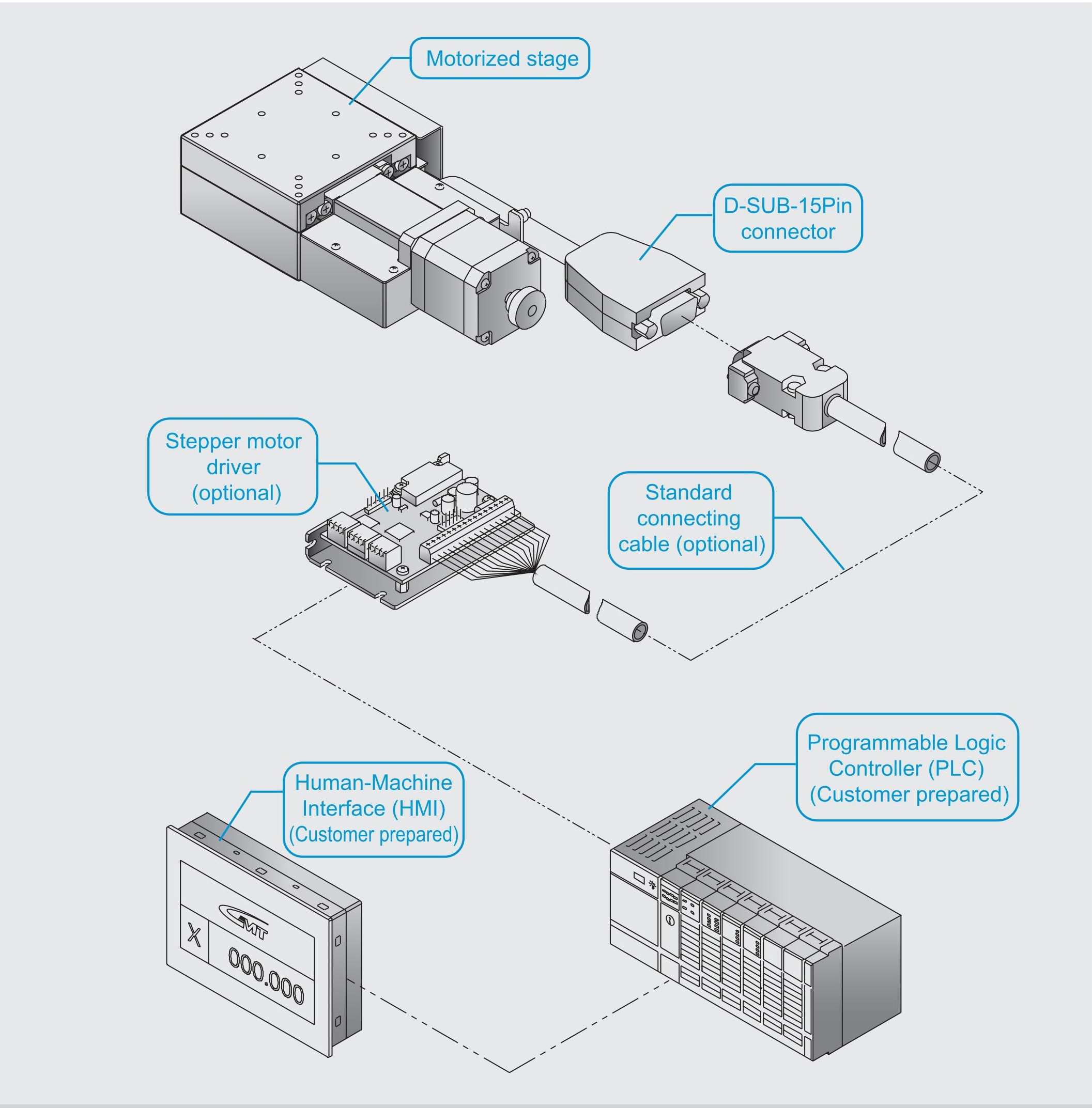
System Configuration Diagram |
|
♦ For detailed specifications, please read the description for the stage and connecting cable. ♦ For selection of driver, please refer to the cross-reference table for the motor/driver of the standard motorized stage or the GMT motor and driver catalog. ♦ The most preferred driver is recommended to be specified by GMT as considerations. For different needs, please choose the suitable driver based on real functional needs.
|
|
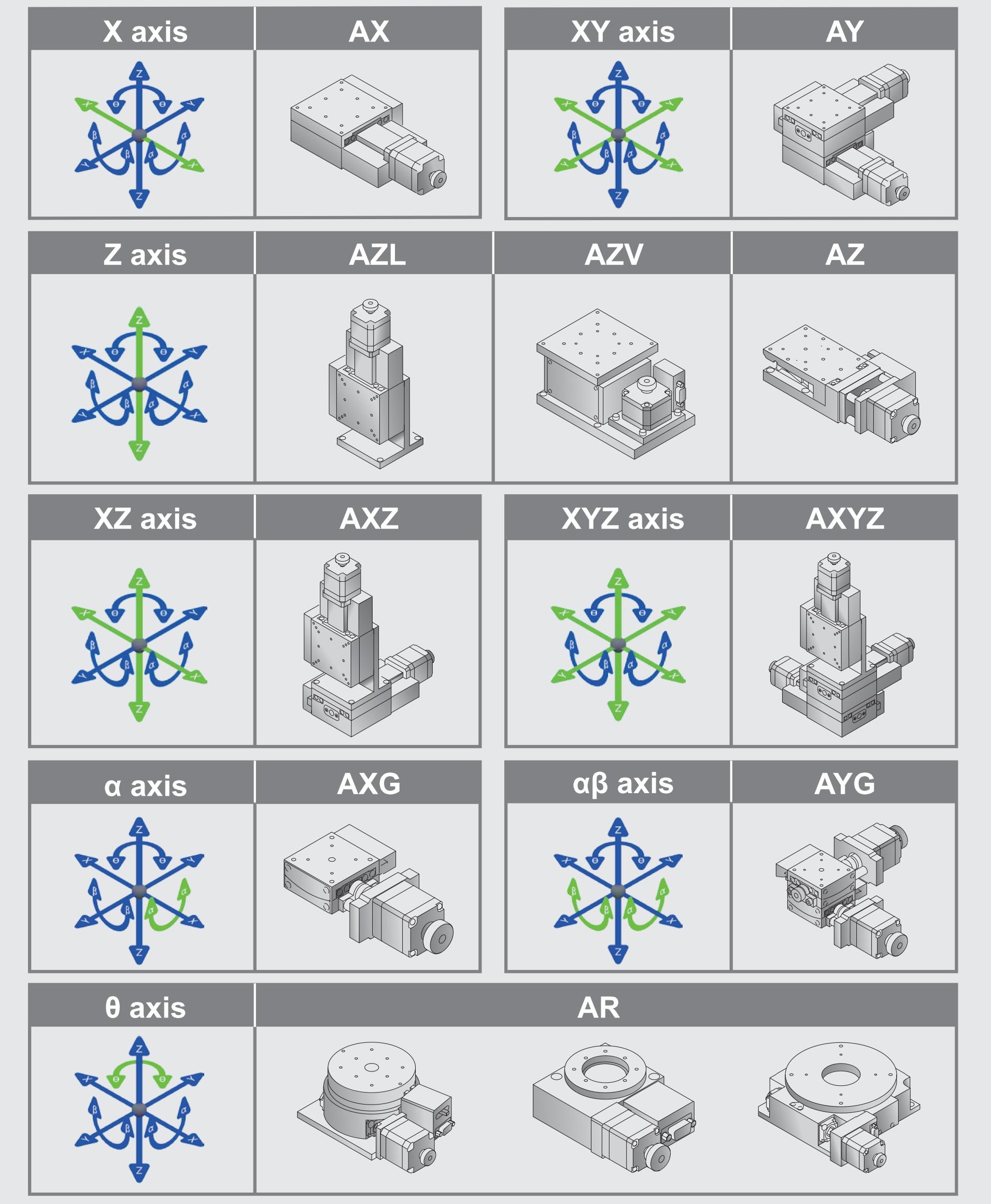
Axis Definition |
|
GMT has defined different axis as the following figuration according to the movement direction: Horizontal movement direction is X and Y axis. Vertical movement direction is Z axis. Movement around X, Y, Z axis is defined to α axis, β axis, and θ axis. Green arrows present the specified axis movement direction.
|
Inquiry - CXC 60 - Ultra Precision


