

Share:


|
Model No. |
CXYZC5050-S2PN-CD-P1 CXYZC5050-F2PN-CD-P1 |
CXYZC5050-S2PN-CD-P2 CXYZC5050-F2PN-CD-P2 |
CXYZC5075-S2PN-CD-P1 CXYZC5075-F2PN-CD-P1 |
CXYZC5075-S2PN-CD-P2 CXYZC5075-F2PN-CD-P2 |
||
|
Mechanical Spec. |
Table Size (mm) |
50 X 50 |
||||
|
Travel Stroke (mm) |
50 |
75 |
||||
|
Drive Type |
Ball screw Ø8 lead 1 mm |
Ball screw Ø8 lead 2 mm |
Ball screw Ø8 lead 1 mm |
Ball screw Ø8 lead 2 mm |
||
|
Rail |
Circular Linear Ball Guiding |
|||||
|
Stage Material / Surface Treatment |
S:Stainless Steel / Nickel Plating F:Carbon Steel / Nickel Plating |
|||||
|
Main Unit Weight (Kg) |
4.39 | 4.12 | ||||
|
Coupling |
FAMCS11.6-5*5 |
|||||
|
Accuracy Level |
P:Precision grade |
|||||
|
Wiring Method |
N:GMT Standard |
|||||
|
Precision Spec. |
Resolution (Pulse) (µm) |
2 (Full) 1 (Half) |
4 (Full) 2 (Half) |
2 (Full) 1 (Half) |
4 (Full) 2 (Half) |
|
|
Max. Speed (Full Step) (mm / sec) |
20 |
40 |
20 |
40 |
||
|
Positioning Presion (µm) |
5 |
7 |
||||
|
Repeatability Precision (µm) |
± 0.5 |
|||||
|
Load Capacity (Kgf) |
7 |
|||||
|
Missed Step (µm) |
1 |
|||||
|
Parallelism (µm) |
15 |
|||||
|
Dynamic Straightness (µm) |
2 |
|||||
|
Dynamic Parallelism (µm) |
10 | |||||
|
Electrical Spec. |
Motor |
Type / Shaft Numbers |
5-phase stepper XY-Axis:☐ 28 double shafts;Z-Axis:☐ 42 double shafts |
|||
|
Brand / Model |
SANYO / XY-Axis:SH5281-7211;Z-Axis:103F5510-8211 |
|||||
|
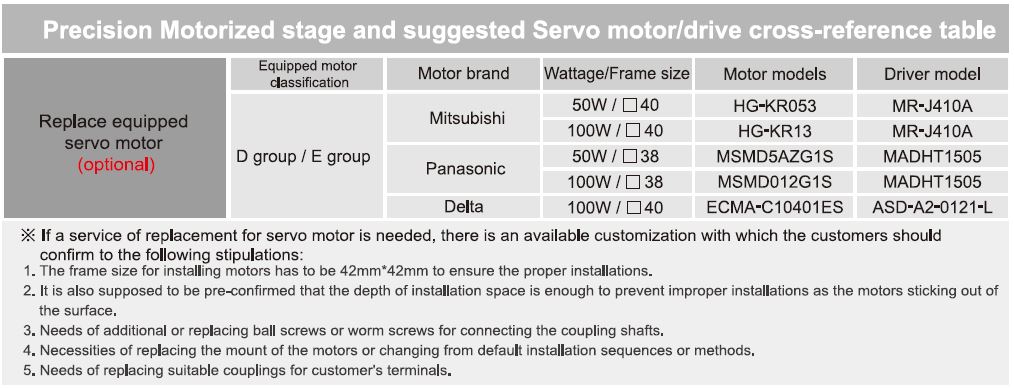
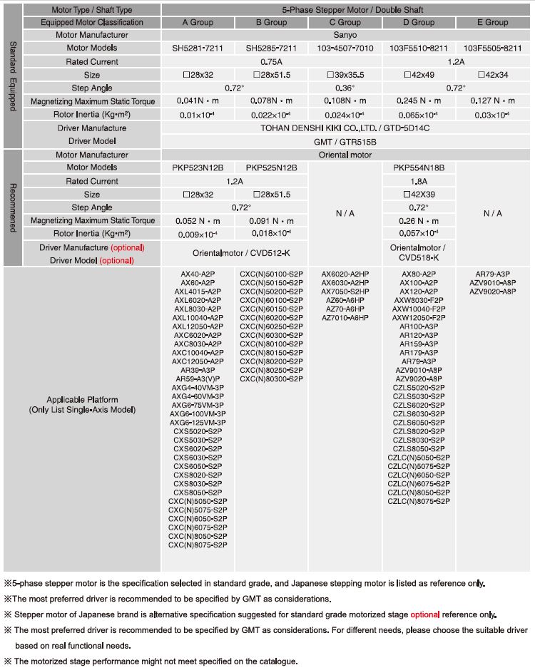
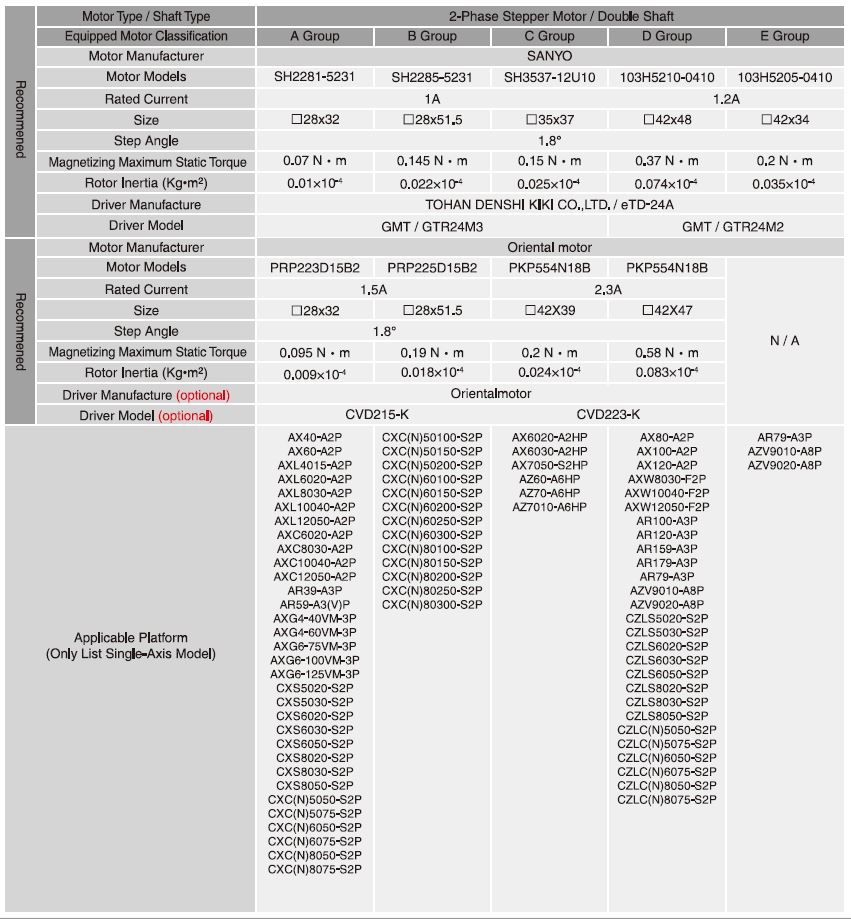
Driver Brand / Model |
Please refer to reference table |
|||||
|
Connector |
Stage Side Connector |
15-Pin male end connetor D-SUB / 12-Pin male end connetor HRS |
||||
|
Controller Side Connector |
15-Pin female end connetor D-SUB / 12-Pin female end connetor HRS (Additional options) |
|||||
|
Sensor |
Origin Sensor |
Photoelectric sensor GMT-sensor |
||||
|
Limit Sensor |
||||||
|
Origin Approximation Sensor |
N / A |
|||||
|
Power Voltage |
24V ± 10% |
|||||
|
Control Output |
NPN open collector output under 24V 8mA |
|||||
|
Output Control |
Testing (sensing):output transistor OFF (closed) |
|||||
| System Configuration Diagram |
|
♦ For selection of the drivers preferred, please refer to the reference table or the catalogue of Motor・Driver. ♦ All of the drivers chosed are the specification of GMT preferred. For different needs, please choose the suitable drivers according to real functional needs.
|

| Axis Definition |
|
GMT has defined different axis as the following figuration according to the movement direction: Horizontal movement direction is X and Y axis. Vertical movement direction is Z axis. Movement around X, Y, Z axis is defined to α axis, β axis, and θ axis. Green arrows present the specified axis movement direction.
|

Motor・driver Reference Table |
|
|
|
|
 |
Inquiry - CXYZC50 - Precision


